ASIA ELECTRONICS INDUSTRYYOUR WINDOW TO SMART MANUFACTURING
Anritsu, KYOCERA Complete First PCI Express® 5.0 Optical Transmission Test
Anritsu Corporation and KYOCERA Corporation completed a successful PCI Express®*1 5.0 (PCIe®5.0) optical transmission test. Specifically, the test employed Anritsu’s Signal Quality Analyzer-R MP1900A and KYOCERA’s on-board optics module. This first* test converted a PCIe® 5.0 (32Gbps transmission speed) electrical signal into an optical signal using an end-point Add-in Card*2 (AIC).
*PCIe® 5.0 Optical transmission test (Surveyed by Anritsu in September 2022)
Test Background
Advanced value-added services, such as 5G, IoT and cloud applications are spreading rapidly. This trend creates unprecedented demand for faster data speeds and larger data capacities. However, today’s power-intensive datacenters face cost and sustainability issues as they increase transmission speeds and capacity.
Specifically, this Anritsu/KYOCERA test converts an electrical signal into an optical signal at an early stage. The process involves mounting an on-board optics module — greatly miniaturized through KYOCERA’s multilayer ceramic technology — close to the host (a MP1900A simulating a CPU output signal for test purposes). The test verified that the E/O-converted signal was transmitted at the PCIe® 5.0 standard 32-Gbps speed to the endpoint located 25m from the host. In addition, the successful optical signal transmission test proved the potential for this technology to reduce datacenter power consumption through lower signal loss.
In the future, signal transmission between servers will not use Ethernet due to power consumption issues and latency. Instead, servers will use direct PCIe® connections. Mainly, operators of next-generation datacenters using PCIe® optical signal transmission will enjoy the business benefits of lower power consumption and reduced latency. With this successful test, Anritsu and KYOCERA are helping to solve the evolving challenges of tomorrow’s digital society.
Demonstration Outline
The demonstration at OFC2023 introduced Anritsu’s MP1900A simulating the CPU host side and KYOCERA’s on-board optics module at an equipment connection with an endpoint AIC. Items “a” through “d” in the below figure are explained as follows:
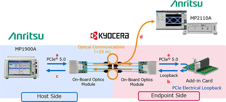
a. The PCIe® 5.0 electrical signal output from the MP1900A is converted into an optical signal by the on-board optics module before transmission. After optical transmission and reconversion back to an electrical signal by the on-board optics module at the 25m distant endpoint side, the electrical signal is connected to the AIC.
b. The AIC switches to Loopback Mode using the signal transmitted through the on-board optics modules by the MP1900A Link Training function.
c. The MP1900A receives the Loopback data from the AIC and confirms the data are error-free.
d. The optical signal transmitted from the on-board optics module is split and input to Anritsu’s Sampling Oscilloscope MP2110A for monitoring to verify that the PCIe® 5.0 optical signal is transmitted correctly.
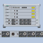
Outline of Anritsu Signal Quality Analyzer-R MP1900A
Specifically, Anritsu’s MP1900A is a high-performance BERT*3 for reception (Rx) tests of high-speed computing and data communications interfaces. These include PCIe®, USB, Thunderbolt™, and 400/800GbE. Meanwhile, Link Training Status State Machine (LTSSM*4) functions are supported by an industry-best level PAM4*5/NRZ*6 PPG for high-quality waveforms, high-sensitivity input ED, high-accuracy jitter generation source (SJ, RJ, SSC, BUJ), and vertical noise generation source (CM-I/DM-I*7 and white noise), facilitating various applications, including compliance and margin tests, as well as troubleshooting.
Outline of Anritsu BERTWave MP2110A
With a built-in CRU*8, the MP2110A 4-ch sampling oscilloscope is the ideal all-in-one solution for analyzing NRZ and PAM4 Eye patterns of 10G-800G optical transceivers and devices. Combining a sampling oscilloscope and CRU in one tester facilitates easy and space-saving operation.
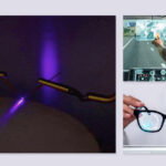
Outline of KYOCERA On-Board Optics Module
On the other hand, due to its miniaturized form factor, KYOCERA’s on-board optics module facilitates easy processor-adjacent mounting. This setup converts electrical signals from the processor at the earliest possible stage and cuts wiring losses when sending/receiving electrical signals. Moreover, this KYOCERA product achieves a first* 512-Gbps transmission band to help datacenters and supercomputers cut power consumption and implement faster speed and larger capacities.
* PCIe® 5.0 product (Surveyed by KYOCERA in September 2022)
Technical Terms
*1 PCI Express® – One bus standard for connecting computers and peripherals; standardized as Gen 1 to Gen 5 according to transmission speed.
*2 Add-in Card – End-point expansion card (memory, NIC, etc.) connected to host with CPU, etc.
*3 BERT – Abbreviation for Bit Error Rate Tester; test instrument for measuring digital signal error rate.
*4 LTSSM – Abbreviation for Link Training Status State Machine; state transition for managing link state of serial bus, such as PCI Express® and USB.
*5 PAM4 – Abbreviation for Pulse Amplitude Modulation; transmission method controlled by changing voltage amplitude (pulse height). PAM4 transmits two data bits in one time slot using four voltage levels.
*6 NRZ – Abbreviation for Non-Return to Zero; one form of digital signal transmission.
*7 CM-I, DM-I – CM-I: Abbreviation for Common Mode Interference; DM-I: Abbreviation for Differential Mode Interference; noise added to signal voltage.
*8 CRU – Abbreviation for Clock Recovery Unit; function for generating trigger signal from input Data signal. Sampling oscilloscopes require trigger signal synchronized to the data signal, but CRU supports waveform monitoring of transmission equipment without trigger signals.
- Share: