ASIA ELECTRONICS INDUSTRYYOUR WINDOW TO SMART MANUFACTURING
Components Packaging Evolves With CASE Trends
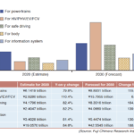
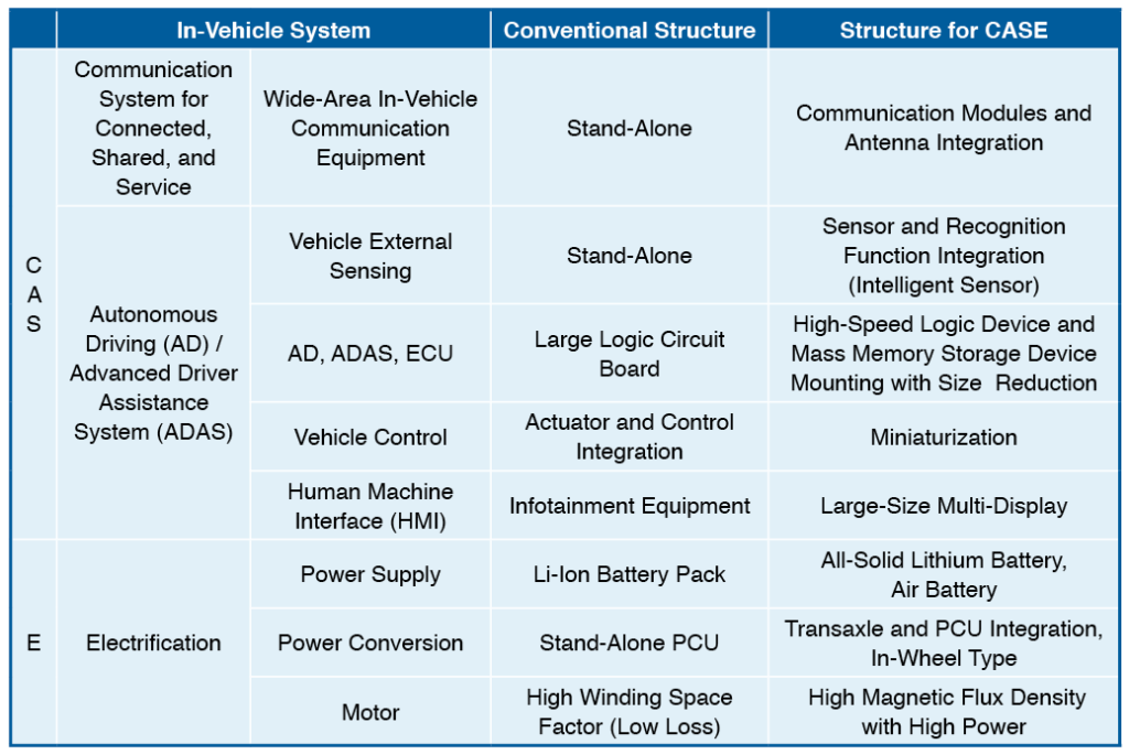
The history of car electronics started with the control of powertrains for internal combustion engines and later on has expanded to the drive safety system, body system, and to intelligent transport systems (ITS) and information system.1) Recently, innovations towards connected, autonomous, shared & services, and electric (CASE) fields have been advancing. Table 1 shows changes in the structure of main in-vehicle equipment towards CASE.
In-Vehicle Equipment for Connected, Autonomous, Shared & Services
As technologies that support connected and shared & services, communications equipment for out-of-vehicle communications have been advancing to feature larger capacities and higher speeds, support fifth-generation (5G) communications and higher frequencies, and integrate modules. The integration of recognition function into on-board cameras, Light Detection and Ranging (LiDAR) sensors, and radars (rendering these devices intelligent) advances as out-of-vehicle sensing devices for achieving autonomous driving functions. Furthermore, the controller constituting integrated control circuits, including autonomous driving electronic control units (ECUs), incorporates high-speed, large-capacity computing elements and large-capacity memories, and the integration of the packaging structure surrounding the elements is reaching the highest level ever.
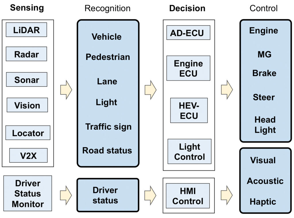
Fig. 1 shows an overview of autonomous driving (AD) and advanced driver-assistance systems (ADAS) system. The system is constructed such that various sensors recognize the conditions of vehicles, pedestrians, lanes, signals, driver, and other; the AD-ECU, engine ECU, and hybrid electric vehicle (HEV)-ECU receive the information, make decisions, and control the engine, motor generator (MG), brakes and steering wheel; and at the same time, the human-machine interface (HI) controller performs the controls between the human and machine through images, sounds, and tactile sense.
Automotive Electronics for Electrification
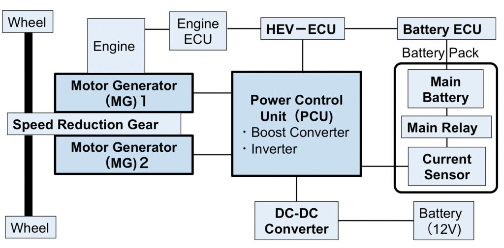
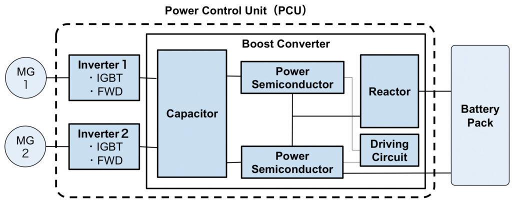
The battery and battery management ECU as power supply system, power control unit (PCU) that controls and drives MG as power conversion system, as well as charging and transformation equipment such as DC/DC converter, are required to achieve higher output density and become smaller and lighter. For example, integration of PCUs that were previously discrete components with transaxle, and their downsizing and higher output density through the adoption of in-wheel construction have been advancing. Fig. 2 shows the structure of in-vehicle equipment in hybrid vehicles, and Fig. 3 shows the detailed inner structure of PCUs. Power semiconductors as basic components of inverters have been shifting from silicon (Si) to silicon carbide (SiC) in pursuit of smaller equipment with higher frequencies. Higher frequency circuits enable the downsizing of the entire equipment, including power circuit, and electric circuit. SiC enables operation in higher temperatures than Si.
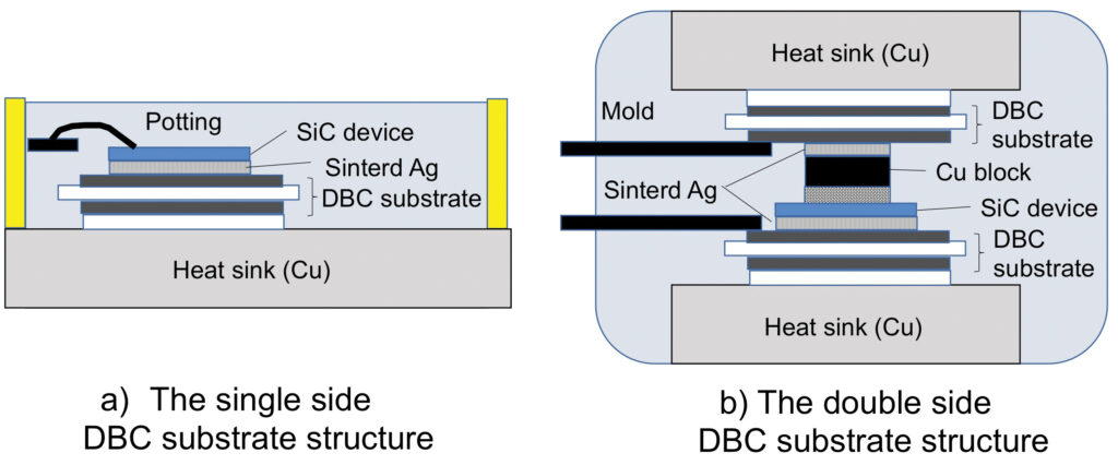
However, there are limits in the reduction of chip size and heat resistance of surrounding packaging components, and therefore, it is important to construct a high heat dissipation packaging structure. Fig. 4 shows examples of heat-dissipation packaging structures for SiC module. They achieve high heat resistance and relaxed stress by joining the direct bonded copper (DBC) with thermal expansion coefficient that is in-between those of silicon and heat sink (copper) using sintered Ag joining with high heat resistance.2-4)
Changes in Packaging Structure in In-Vehicle Equipment
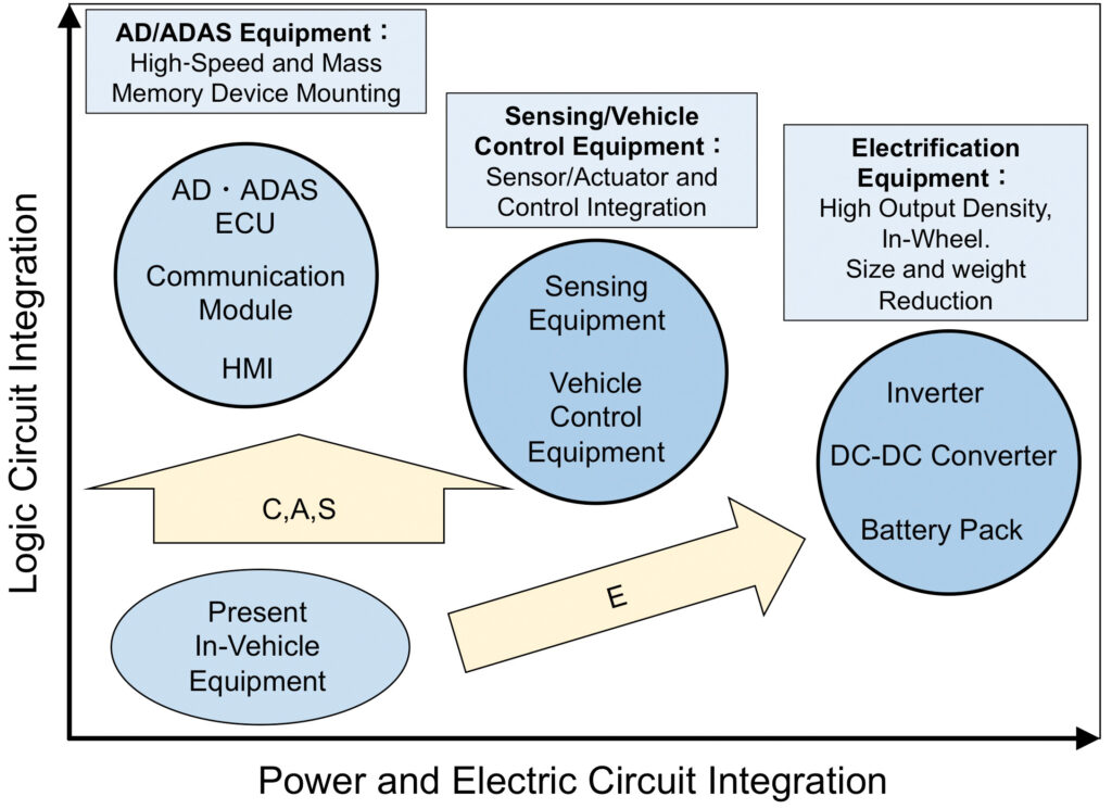
Fig. 5 shows changes in the packaging structure of in-vehicle equipment toward the shift to CASE. Higher integration of logic circuit for HMI devices, including AD/ADAS-ECU, communication module, and passenger condition sensing and display devices advances compared with those in existing in-vehicle equipment. Meanwhile, with electrification devices, including inverter, DC/DC converter, and battery pack, higher integration of power circuit and electric circuit is required, along with the higher integration of logic circuit.
References:
1)Mitsuharu Kato: “Overview of the History of Car Electronics and Prospects for the Future,” Journal of Japan Institute of Electronics Packaging, 19-5 (2016), 289-300.
2)Masakazu Tanaka, Atsuyuki Hiruma, Atsusi Umeda, Shun Ohkijima, Keisuke Tani, Akihiro Imura: “Electrification Technologies for Vehicles in Denso,” Denso Technical Review, 22(2017), 9-20.
3)Masafumi Horio, Yuji Iizuka, Yoshinari Ikeda: “Packaging Technologies for SiC Power Modules,” Fuji Electric Journal, 84-5(2011),336-339.
4)Yoshinari Ikeda, Yoshitaka Nishimura, Eiji Mochizuki, Yoshikazu Takahashi: “About Present Condition and Outlook of Packaging Technology for a Power Semiconductor Module”, Journal of Smart Processing, 4-1(2015),46-50.
5)Toshihiro Miyake: “Trends of Car Electronics and Power Electronics Packaging Technologies,” Journal of Smart Processing, 9-6(2020), 255-258.
- Share:


About This Article:
The author is, Toshihiro Miyake, Representative, e-mail: fr64fx1276@icloud.com The original version of this article appeared in 9-6(2020) 255-258 of the Journal of Smart Processing. The author extracted essential points and were brushed up courtesy of the Smart Processing Society.5)